

Geogrids are among the most prominent and widely used geosynthetic materials in geotechnical and civil engineering, employed to enhance the performance of soil structures, increase bearing capacity, and improve overall project stability. These materials, with their regular mesh structure, serve the purpose of soil reinforcement and stabilization. Among the different types of geogrids, uniaxial and biaxial geogrids are extensively used in various projects, each possessing unique characteristics and specific applications.
It is important to note that, contrary to common belief, geogrids do not have a single, unified classification. They can be categorized based on various criteria such as polymer type, manufacturing method, mesh structure, and even engineering performance. This diversity in classification and properties makes the selection and optimal design of geogrids a specialized challenge for engineers. In this article, a comprehensive comparison is made between uniaxial and biaxial geogrids in terms of structure, technical specifications, engineering behavior, performance mechanisms, and applications. In addition, key considerations for optimal selection and design based on project conditions are discussed.
Lorem ipsum dolor sit amet, consectetur adipiscing elit. Ut elit tellus, luctus nec ullamcorper mattis, pulvinar dapibus leo.
1- Definition and Structure of Geogrids
Geogrids are polymeric materials with a regular grid-like structure, produced in the form of meshes with square, rectangular, or even triangular apertures.
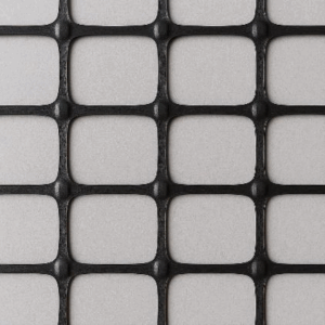

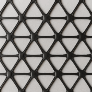
Figure 1: Types of geogrids with square, rectangular, and triangular apertures
Uniaxial Geogrid
In this type of geogrid, the tensile strength is primarily concentrated in one direction (usually the longitudinal direction). Its structure is designed such that the main ribs are stretched in the longitudinal direction, while the tensile strength in the transverse direction is significantly lower compared to the longitudinal direction.
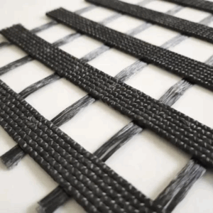
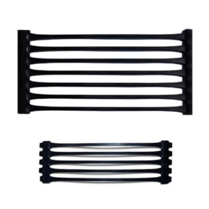
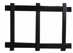
Figure 2: Types of uniaxial geogrids—woven, extruded, and welded
Biaxial Geogrid
This type of geogrid exhibits nearly equal and high tensile strength in both the longitudinal and transverse directions. Its structure is designed to provide reinforcement and stability along both axes.
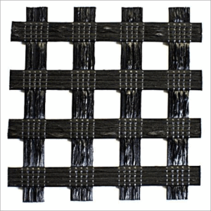


Figure 3: Types of biaxial geogrids—woven, extruded, and welded
Manufacturing Structure of Geogrids (Uniaxial and Biaxial)
Geogrids are classified into three main categories based on their manufacturing technology, each of which can be produced in uniaxial or biaxial forms.
1- Extruded Geogrids
In this method, a polymer sheet (typically polyethylene (PE) or polypropylene (PP)) is punched into a grid pattern and then stretched in one or two directions.
Uniaxial Extruded Geogrid
The punched polymer sheet is stretched only in one direction, resulting in a significant increase in tensile strength along that direction.
Biaxial Extruded Geogrid
The punched sheet is first stretched in one direction and then in the perpendicular direction, producing similar tensile strength in both directions.
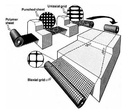
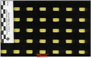
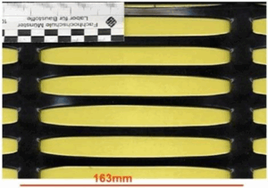
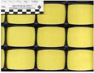
Figure 4: Manufacturing process of uniaxial and biaxial geogrids by the extrusion method
2- Woven Geogrids
In this method, high-strength polymer fibers or strips (commonly polyester, polypropylene, or fiberglass) are woven together in both the warp and weft directions. A protective coating (such as PVC or polyethylene) is then applied to the grid to enhance durability and chemical resistance.
Woven geogrids can be either uniaxial or biaxial: if the alignment and thickness of the fibers are dominant in one direction, the geogrid will be uniaxial; if the arrangement and number of fibers are similar in both directions, a biaxial geogrid is produced.
This type of geogrid is particularly suitable for projects that require flexibility or compatibility with specific chemical conditions.
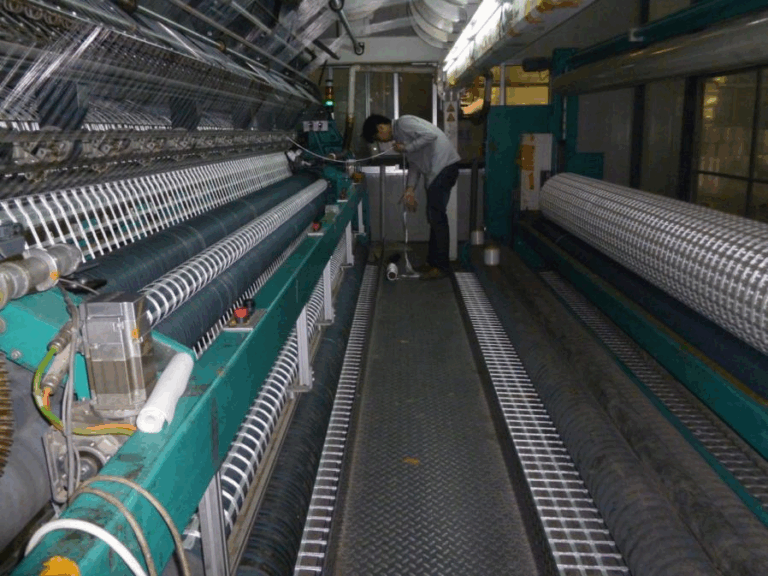
Figure 5: Weaving machine for manufacturing woven geogrids
3- Welded/Bonded Geogrids
In this technology, stiff polymer strips are placed perpendicular to each other and joined at their intersections using thermal welding or special adhesives. Welded geogrids can be manufactured as uniaxial or biaxial depending on the number of strips in each direction. The biaxial type is primarily used for subgrade stabilization and large-area applications.
These products are generally more rigid and stiff, making them suitable for projects where control of lateral deformations and resistance to impact are critical.

Figure 6: Ultrasonic welding machine for bonding geogrid strips.
2- Engineering Behavior and Performance Mechanism
2-1- Uniaxial Geogrid
Tensile Strength: Very high in one direction (usually longitudinal), suitable for absorbing and transferring large tensile stresses in that direction.
Stiffness and Ductility: Greater stiffness along the longitudinal axis, with relative flexibility in the transverse direction.
Performance Mechanism: Primarily reinforces soil or structures along a single axis (for example, in retaining walls, steep soil slopes, or embankments with limited geometry).
2-2- Biaxial Geogrid
Tensile Strength: High and uniform strength in both longitudinal and transverse directions, enabling two-dimensional stress distribution within the soil or aggregate bed.
Stiffness and Ductility: Uniform stiffness and strength along both axes, providing a more balanced performance under biaxial loading conditions (e.g., traffic loads).
Performance Mechanism: Transfers and distributes applied loads in both axes, making it suitable for projects with widespread load distribution (such as road subgrades, foundations, railway tracks, airport runways, and similar applications).
3- Comparison of Applications for Uniaxial and Biaxial Geogrids
In civil and geotechnical engineering projects, uniaxial and biaxial geogrids are considered the primary types, each with specific areas of application. Due to their high tensile strength in a single direction, uniaxial geogrids are mainly used in cases where loading and soil reinforcement are required along a predominant axis, such as retaining walls and steep slopes. Conversely, biaxial geogrids, with their balanced strength in two perpendicular directions, are highly suitable for stabilizing and reinforcing roadbeds, highways, and railway tracks. Selecting the appropriate type of geogrid based on loading conditions, project objectives, improvement of structural performance, enhanced stability, cost reduction, and similar factors has a significant impact on project success. The following outlines typical applications for uniaxial and biaxial geogrids.
3-1- Applications of Uniaxial Geogrids
Mechanically Stabilized Earth Walls (MSEWs): Due to the concentration of load and lateral earth pressure in a single direction (behind the wall), uniaxial geogrids are the optimal choice for absorbing and transferring tensile forces along the required axis.

Figure 7: View of a geogrid-reinforced mechanically stabilized earth (MSE) wall
Steep Slopes and Embankments: Stabilization and reinforcement of soil layers requiring high tensile strength in a single direction, such as in road construction projects in mountainous areas.
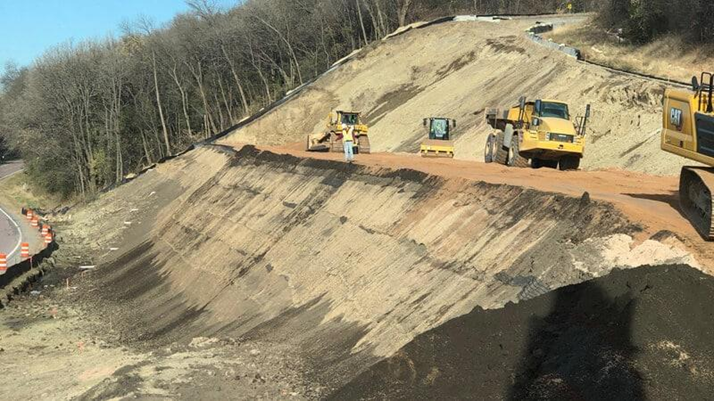
Figure 8: View of a reinforced embankment
Stability of High Soil Structures and Trenches: In projects where the dominant force is applied in a specific direction and there is a need to control lateral displacement and soil settlement.
3-2- Applications of Biaxial Geogrids
Reinforcement of Roadbeds, Highways, and Pavements: Providing a stable foundation resistant to settlement, distributing traffic loads, increasing bearing capacity, and reducing the thickness of pavement layers.
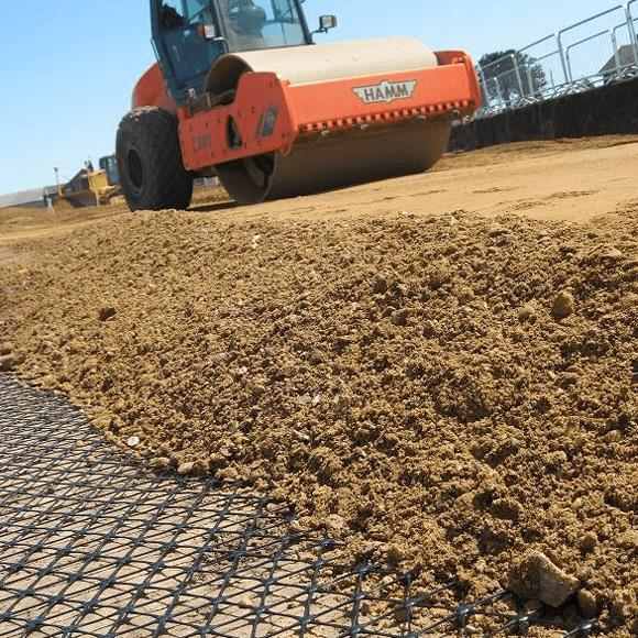
Figure 9: Use of geogrids for subgrade reinforcement in road construction projects
Subgrade Construction for Railways and Airports: Reinforcement and stabilization of the foundation against dynamic and repetitive loads with multidirectional load distribution patterns.
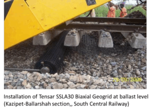

Figure 10: Application of geogrids in railway track subgrades
Stabilization of Weak, Soft, and Marshy Soils: Uniform distribution of loads and prevention of localized failures in saturated and unsuitable soils.
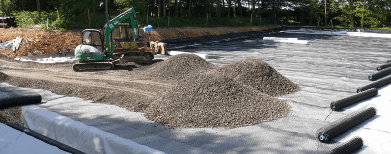
Figure 11: Use of geogrids for reinforcement of weak subgrades
3-3- Comprehensive Comparison of Uniaxial and Biaxial Geogrids
To provide a clearer understanding of the characteristics and applications of uniaxial and biaxial geogrids—and to facilitate the comparison process for readers—all the points and information presented in the previous sections are systematically compiled and presented in the form of a table. This table allows the differences and similarities between the two types of geogrids to be easily identified and assessed, enabling proper selection based on specific project requirements.
Characteristics | Uniaxial Geogrid | Biaxial Geogrid |
Direction of Tensile Strength | Only in one direction (longitudinal) | Equal in both directions |
Aperture Shape | Mostly rectangular and elongated | Mostly square or nearly square |
Manufacturing Method | Extruded, woven, or welded | Extruded, woven, or welded |
Load Transfer | Load transfer in one direction (the direction with the highest tensile strength) | Load transfer and distribution in both directions |
Key Applications | Retaining walls, steep slopes | Roads, railways, airports, bridge abutments, subgrade reinforcement |
4- Design Differences Between Uniaxial and Biaxial Geogrids in Civil Projects
During the design process, the selection of the geogrid type must be based on the nature of the applied forces, soil type, and the expected performance. The design differences between these two types of geogrids are primarily related to several key factors.
4-1- Design with Uniaxial Geogrids
Load Pattern: In reinforced earth retaining walls or steep slopes, the primary load is horizontal, and the geogrid must resist lateral earth pressure.
Key Design Parameter: Ultimate tensile strength of the geogrid in the longitudinal direction (Tult) and allowable strain.
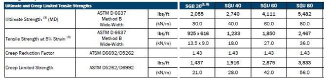
Figure 12: Sample datasheet of a uniaxial geogrid
Installation Direction: The geogrid must be installed in the direction of maximum tensile strength, as any twisting or deviation from the principal design direction will significantly reduce its effectiveness.
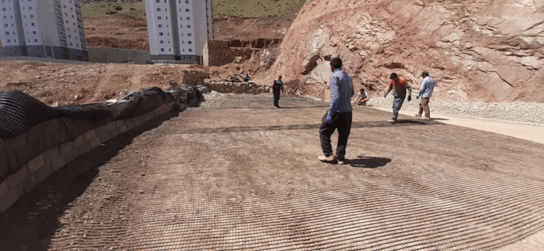
Figure 13: Installation of uniaxial geogrids (the main tensile strength must be perpendicular to the wall face)
Reinforcement Length: In retaining walls, the length of the geogrid is typically considered to be 70% to 90% of the wall height in order to effectively transfer lateral earth pressure.
Table 2: Minimum Reinforcement Lengths (FHWA-NHI-10-024)
Loading and Structural Conditions | Minimum L/H |
Static loading with or without live surcharge | 0.7 |
Sloped embankment | 0.8 |
Seismic loading | 0.8-1.1 |
4-2- Design with Biaxial Geogrids
Load Pattern: In roadbeds or railway tracks, loads are applied in two perpendicular directions (longitudinal and transverse), and uniform distribution of forces is crucial.
Key Design Parameters: Ultimate tensile strength in both directions (Tult,x and Tult,y) as well as geogrid performance at 2% and 5% strain.
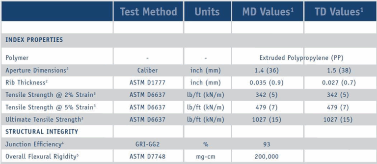
Figure 14: Sample datasheet of biaxial geogrids
Installation Direction: Biaxial geogrids are generally less sensitive to installation direction compared to uniaxial geogrids, which allows for faster installation.
Reinforcement Length: In subgrade reinforcement, the length of the geogrid layer depends on the entire width of the path, and the layer is continuously spread beneath the whole subgrade.
5- Advantages and Disadvantages of Uniaxial and Biaxial Geogrids
5-1- Advantages of Uniaxial Geogrids
- Achieve very high tensile strength in one direction
- Ideal for retaining wall and steep slope projects
- Cost-effective for projects with unidirectional loading
5-2- Disadvantages of Uniaxial Geogrids
- Not effective for distributing multidirectional loads
- Requires high precision in alignment and installation
- More vulnerable than biaxial geogrids due to low tensile strength in the secondary direction
5-3- Advantages of Biaxial Geogrids
- Uniform load distribution and increased subgrade stiffness
- Reduced thickness of embankment layers and material savings
- Faster installation and less sensitivity to construction errors
5-4- Disadvantages of Biaxial Geogrids
- Higher cost compared to uniaxial geogrids
- Heavier rolls compared to uniaxial geogrids of similar strength
- Limited aperture sizes for specific aggregate gradations
- Performance depends on soil quality and proper compaction
6- Key Considerations for Geogrid Selection
The selection of the appropriate type of geogrid depends on the following factors:
Nature and Direction of Loading: The most important principle is to match the geogrid’s tensile strength with the loading direction.
Soil Conditions: In loose or granular soils, the mechanical interlock between the soil and the geogrid is critical. The aperture size and shape of the geogrid should be compatible with the soil gradation to ensure proper interlock.
Expected Service Life and Environmental Conditions: It is essential to select polymers that are resistant to environmental factors (moisture, chemicals, UV, etc.) throughout the expected service life and according to project conditions.
Construction and Economic Considerations: Cost, ease of installation, availability of the geogrid type, and construction capabilities should be taken into account.
Standard Compliance: Always use geogrids with valid international certifications (such as ASTM, EN, ISO, etc.).
7- Conclusion
The comparison between uniaxial and biaxial geogrids demonstrates that each type has its own advantages and limitations depending on the project type, loading conditions, and performance requirements. Uniaxial geogrids are the ideal choice for projects requiring high tensile strength in a single direction, such as retaining walls and steep soil slopes. In contrast, biaxial geogrids, with their uniform performance in both directions, are the best option for stabilizing roadbeds, railway tracks, and large areas. Proper selection of geogrid type, based on an understanding of the mechanical behavior and application of each, is a key factor in ensuring the success and long-term stability of soil structures in civil and geotechnical engineering projects.
8- References
Shukla, S.K., An Introduction to Geosynthetic Engineering, CRC Press, 2025.
Koerner, R.M., Designing with Geosynthetics, 6th Edition, Xlibris, 2012.
FHWA-NHI-10-024: Design and Construction of Mechanically Stabilized Earth Walls and Reinforced Soil Slopes.